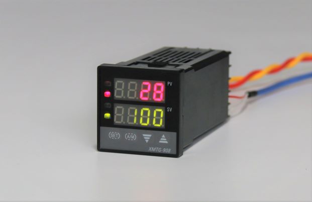
XMT-908 series temperature controller
XMT□-908
Technical specification
1, Measurement deviation: ≤±0.5%F·S±1B
2, Cold end compensating deviation: ≤±2.0℃
3, Sampling cycle: 0.5S
4, Control cycle: relay output 2~120S , other is 2S.
5, Relay output contact capacity: AC220V/5A (resistance load) or AC220V/0.3A (perceptual load).
6, Driving controllable pulse output: ≥3V scope, ≥40us width’s over zero or trigger contact pulse.
7, Driving solid relay signal output: driving electric current≥15mA, voltage≥9V.
8, Continuous PID: 0~10mA (load 500±200Ω), 4~20mA (load 250±100Ω), or 0~5V (load≥100kΩ) , 1~5V (load≥100kΩ).
9, Power supply: AC85V~242V, 50/60Hz.
10, Working condition: temperature 0~50.0℃, relative humidity≤85%RH, without corrode and strong electric radiation.
Product code:
XMT □ 9 □ 8 □
(1) (2) (3) (4) (5)
(1) Frame dimensions (mm)
“A” = 96×96×110
“D” = 72×72×110
“E” = 48×96×110
“F” = 96×48×110
“G” = 48×48×110
“S” = 80×160×130
(2) “9” = Serial number, PV and SV display with 4 digits
(3) Alarms
“0” = no set alarm
“1” = one alarm
“3” = two alarms (upper limit, lower limit, deviation alarms)
“5” = voice alarm
(4) Input
“8” = universal input model
(5) Output
Blank = Relay contact output
“A” = Single-phase over-zero trigger adjustment
“A3” = Three-phase over-zero trigger adjustment
“B” = Single-phase shift-phase trigger adjustment
“B3” = Three-phase shift-phase trigger adjustment
“C”= 0-10mA or 4-20mA constant output
“G” = solid state relay output


